If everything is working correctly, Router 2 and Router 3 should learn the loopback route:
1.1.1.1/32
through EIGRP.
You should also be able to telnet into Router 1 from Router 2 and Router 3.
The Problem
Here’s where things get interesting.
A network engineer made a configuration mistake somewhere in this lab.
The routers are no longer exchanging routes correctly.
Users are reporting connectivity problems.
Your task is to troubleshoot the network and identify the issue.
Symptoms
You may notice:
Missing EIGRP routes
Failed telnet attempts
Missing neighbor adjacencies
Incomplete routing tables
Troubleshooting Challenge
Without looking ahead:
Verify interface connectivity
Check IP addressing
Verify interfaces are up
Check EIGRP neighbors
Compare EIGRP configurations between routers
Determine why routes are not being exchanged
Helpful commands:
show ip eigrp neighbors
show ip protocols
show running-config
show ip route
Think Before You Scroll
Try to solve the issue yourself before revealing the answer.
Real networking jobs often involve tiny mistakes that cause major outages.
This lab simulates exactly that scenario.
Solution
The issue is on Router 2.
Instead of:
router eigrp 1
the router was configured with:
router eigrp 2
Because EIGRP autonomous system numbers must match between neighbors, Router 2 fails to form adjacencies with the other routers.
As a result:
Routes are not exchanged
Neighbor relationships fail
Router 3 never learns the loopback route
Telnet connectivity breaks
Correcting the AS number restores routing immediately.
Why This Is Important
This is one of the most common routing protocol mistakes beginners make.
The configurations can look almost identical, yet one incorrect number completely breaks dynamic routing.
Learning how to systematically troubleshoot issues like this is what separates someone who memorizes commands from someone who truly understands networking.
Learning how to configure DTP Packet Tracer environments properly is one of the most underrated skills you can develop. Most people rush through trunking concepts, memorize a few commands, and move on. But if you truly take the time to configure DTP Packet Tracer labs in depth, you begin to understand how switches actually communicate, negotiate, and sometimes fail.
This guide is designed to go beyond surface-level explanations. You’re not just going to configure DTP Packet Tracer once and call it a day. Instead, you’ll repeatedly configure DTP Packet Tracer across multiple interfaces, explore different combinations, intentionally break things, and fix them again. That repetition is what builds real understanding.
By the time you finish, the phrase configure DTP Packet Tracer won’t just be a concept—it’ll represent a skill you actually own.
Why You Should Learn to Configure DTP Packet Tracer the Right Way
Previously, we wrote about VTP, how to break it and how to fix it. When you first hear about trunking, it seems simple. You connect two switches, enable trunking, and VLANs pass through. But once you begin to configure DTP Packet Tracer labs, you realize that trunking is not just a switch you turn on or off. It’s a negotiation process.
DTP controls whether a port becomes a trunk or stays an access port. And when you configure DTP Packet Tracer environments with different modes on each side, the outcome depends entirely on how those modes interact.
This is why repeatedly practicing how to configure DTP Packet Tracer is so important. You’re training yourself to think like a switch. You’re learning how it decides, how it responds, and how it behaves when configurations don’t align.
Lab Setup: Preparing to Configure DTP Packet Tracer
Before you begin to configure DTP Packet Tracer, you need a topology that allows you to test multiple scenarios at once.
Start by adding:
One router (2901)
Two switches (3650)
Connect the router to Switch1. Then connect Switch1 to Switch2 using multiple links, such as interfaces g1/0/2 through g1/0/9.
This setup allows you to configure DTP Packet Tracer across several ports simultaneously, which is critical for observing different behaviors side by side.
From your notes, all ports begin as access ports using dynamic auto behavior . This is the perfect baseline when you configure DTP Packet Tracer because it reflects how switches behave by default.
Understanding the Modes Before You Configure DTP Packet Tracer
Before you configure DTP Packet Tracer links, you need to understand the modes you’ll be working with.
Dynamic auto is passive. It waits. It does nothing unless the other side initiates trunking.
Dynamic desirable is active. It tries to form a trunk immediately.
Static trunk forces trunking regardless of negotiation.
Nonegotiate disables DTP entirely.
When you configure DTP Packet Tracer, you’re really testing how these modes interact with each other. That interaction determines everything.
First Scenario: Auto Meets Desirable
To begin, configure DTP Packet Tracer on interface g1/0/3.
Set Switch2 to dynamic desirable while Switch1 remains dynamic auto.
As soon as you configure DTP Packet Tracer this way, the desirable side initiates trunking and the auto side accepts. The result is a trunk.
This is one of the most important combinations when you configure DTP Packet Tracer because it demonstrates how negotiation actually works.
When you verify the interface, you’ll see that the operational mode becomes trunk. This confirms that your attempt to configure DTP Packet Tracer was successful.
Second Scenario: Desirable Meets Desirable
Now configure DTP Packet Tracer on both sides of another interface, such as g1/0/4, using dynamic desirable.
When you configure DTP Packet Tracer this way, both sides actively try to form a trunk. There is no waiting. The trunk forms immediately.
This scenario reinforces a key idea. When you configure DTP Packet Tracer, the behavior is not determined by one side alone. Both sides matter.
Third Scenario: Static Trunk with No Negotiation
Next, configure DTP Packet Tracer using static trunk mode combined with nonegotiate.
When you configure DTP Packet Tracer like this, the link becomes a trunk without any negotiation at all.
This is how trunking is often configured in real networks. Instead of relying on DTP, administrators manually define trunk ports for better security.
Even though you are still practicing how to configure DTP Packet Tracer, this step teaches you what happens when DTP is removed from the equation entirely.
Fourth Scenario: Mixed Configurations
Now things get more interesting.
Configure DTP Packet Tracer so that one side is dynamic desirable and the other side is a static trunk with no negotiation.
The trunk still forms. Why? Because the static trunk forces the link into trunk mode.
But now reverse the situation.
Configure DTP Packet Tracer so that one side is dynamic auto and the other side is nonegotiate. Suddenly, nothing happens. No trunk forms.
This is one of the most important lessons you’ll learn when you configure DTP Packet Tracer. Not all mismatches are obvious. Some quietly fail.
Extending VLANs After You Configure DTP Packet Tracer
Once you successfully configure DTP Packet Tracer and form trunk links, the next step is to pass VLAN traffic across them.
Create VLAN 2 and enable it. Then allow VLAN 2 on your trunk ports.
At this point, your efforts to configure DTP Packet Tracer begin to pay off. The trunks you created now serve a real purpose—carrying VLAN traffic.
Breaking the Network After You Configure DTP Packet Tracer
To truly understand what you’ve done, you need to break it.
Take one of your trunk ports and reconfigure it as an access port in VLAN 2.
Now the link is mismatched. One side thinks it’s a trunk. The other side thinks it’s an access port.
When you configure DTP Packet Tracer incorrectly like this, the network begins to behave unpredictably. Spanning tree may react. Traffic paths may change.
From your notes, traffic can still traverse unexpected paths when trunks are broken . This is exactly what you want to observe.
Observing Traffic Flow
Switch to simulation mode and send traffic across the network.
Because you took the time to configure DTP Packet Tracer and then break it, you can now observe how the network adapts.
This is where the learning becomes real. You’re no longer just configuring—you’re analyzing behavior.
Fixing the Network
Now restore the trunk.
Reconfigure the broken port using dynamic desirable and allow VLAN 2.
As soon as you configure DTP Packet Tracer correctly again, the trunk reforms. The mismatch disappears. The network stabilizes.
This reinforces a powerful concept. When you configure DTP Packet Tracer properly, the network behaves predictably. When you don’t, it doesn’t.
Repetition Builds Mastery
At this point, you should repeat the process.
Configure DTP Packet Tracer on different ports using different combinations. Observe the results. Break things again. Fix them again.
The more you configure DTP Packet Tracer, the more natural it becomes.
Real-World Perspective
In production environments, many engineers disable DTP entirely and use static trunking. This reduces risk and improves security.
However, even if you don’t use DTP in real networks, understanding how to configure DTP Packet Tracer is still critical. Because you will encounter it. And when you do, you need to understand how it works.
Final Thoughts
Learning how to configure DTP Packet Tracer is not about memorizing commands. It’s about understanding behavior.
Every time you configure DTP Packet Tracer, you’re training yourself to think like a network device. You’re learning how switches negotiate, how they fail, and how they recover.
And that understanding is what separates beginners from professionals.
So don’t just configure DTP Packet Tracer once. Do it again. Test new combinations. Break things intentionally. Fix them confidently.
Because the more you configure DTP Packet Tracer, the more everything else in networking starts to make sense.
Follow along lab:
In packet tracer:
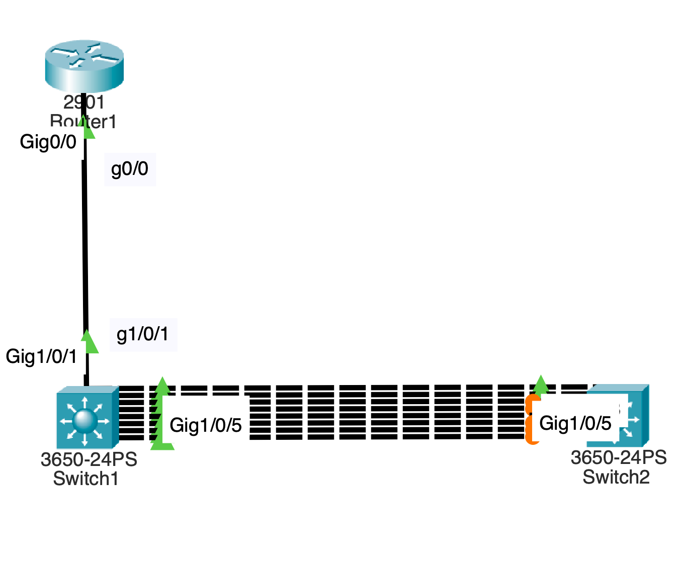
Drag a router 2901 into the logical topology. Drag 2 3650 switches into logical topology. Name them Router1 which is in front of switch1 and switch2. Connect g1/0/1 to g0/0 from switch1 to router using a straight through cable.
Connect switch2 to switch1 using a crossover cable. Connect g1/0/2 to g1/0/2 Do the same for g1/0/3 ,4, 5, 6, 7, 8 and 9. You should have 4 connections between both switches. In terms of DTP all physical swichports are configured to be static access ports with dynamic auto configured. Leave port g1/0/2 as is on both sides of the connection. Configure port g1/0/3 as dynamic desirable on switch 2..
Commands:
En Conf t Int g1/0/3 Switchport mode dynami des End
Configure switchport g1/0/9 to be dynamic desirable.
Commands:
En conf t int g1/0/9 switchport mode dyn de switchport trunk allowed vlan 2
Do the same on switch2.
Now break the trunk so that it becomes a Native VLAN mismatch.
Commands:
switchport mode access switchport access vlan 2
On both switches, pull up spanning tree summary to see validate that 6 vlan ports are forwarding on switch2 while 3 ports are blocking on and 2 ports are forwarding on switch1 for vlan 2. On Router1, configure an ip address on interface port g0/0.
Router>en Router#conf t Router(config)#int g0/0 Router(config-if)#ip ad Router(config-if)#ip address 10.0.0.1 255.255.255.0
On switch1, configure an ip address on vlan 2 for management address.
Commands:
Switch#conf t Switch(config)#int vlan 2 Switch(config-if)#ip address 10.0.0.2 255.255.255.0 Switch(config-if)#
Change the access port to a trunk port with vlan 2.
Commands:
Switch#conf t Enter configuration commands, one per line. End with CNTL/Z. Switch(config)#int g1/0/9 Switch(config-if)#switchport trunk allowed vlan 2 Switch(config-if)#
Progress through the simulation as icmp continues.
VLAN Hopping VTP Attack and Recovery in a Campus Network (VTP Configuration In Cisco Packet Tracer)
If you are learning networking or working toward your CCNA, understanding vtp configuration in cisco packet tracer is essential. It’s one of those topics that seems simple at first—until you see how badly things can go wrong.
In a real network, a single mistake in vtp configuration in cisco packet tracer can wipe out every VLAN across multiple switches. That’s not just a misconfiguration—it’s a full-blown outage.
This lesson walks through a complete campus network lab where VLANs are built, broken, and restored. Along the way, you’ll see exactly how a VTP-based attack works and how proper vtp configuration in cisco packet tracer allows you to recover from it.
Why VTP Can Be Dangerous
VTP (VLAN Trunking Protocol) is designed to make VLAN management easier. Instead of configuring VLANs manually on every switch, you configure them once and let VTP distribute the information.
That’s where vtp configuration in cisco packet tracer becomes both powerful and risky.
VTP uses something called a revision number. Every time a VLAN change is made, the revision number increases. Switches trust the device with the highest revision number and accept its VLAN database as the truth.
Now imagine introducing a switch with a higher revision number—but no VLANs configured. That empty database gets pushed across the network, and suddenly everything is gone.
That’s the core idea behind this lab.
Building the Campus Network
To understand how vtp configuration in cisco packet tracer behaves in a real environment, you first need a structured topology.
This lab includes:
A multilayer switch acting as the core
Two access layer switches
Four PCs across different VLANs
The setup follows a standard campus design where the core switch handles routing and VLAN management, while access switches rely on it.
The full configuration process is based on the lab steps towards the end of this post , which guide the entire topology build and recovery steps.
Configuring the Core Switch
The core switch is where your vtp configuration in cisco packet tracer begins.
First, enable Layer 3 functionality:
ip routing
Then define the VTP domain:
vtp domain havoc
Every switch that participates in vtp configuration in cisco packet tracer must share this domain name.
Next, configure VLAN interfaces with IP addresses so the switch can route traffic between them:
VLAN 1 → 10.0.1.1
VLAN 2 → 10.0.20.1
VLAN 3 → 10.0.30.1
VLAN 4 → 10.0.40.1
VLAN 5 → 10.0.50.1
Bring each interface up, and now your core is ready to distribute VLAN information using vtp configuration in cisco packet tracer.
Enabling Trunk Links
VLAN information doesn’t magically move between switches—it travels over trunk links.
So part of proper vtp configuration in cisco packet tracer is enabling trunking:
Assign management IP addresses and a default gateway so the switches can be managed remotely.
At this point, your vtp configuration in cisco packet tracer is fully functional.
Assigning PCs to VLANs
Each PC is placed into a different VLAN:
VLAN 2 → 10.0.20.20
VLAN 3 → 10.0.30.30
VLAN 4 → 10.0.40.40
VLAN 5 → 10.0.50.50
Once configured, you should be able to ping between VLANs, confirming that your vtp configuration in cisco packet tracer and inter-VLAN routing are working correctly.
The Breaking Point: Simulating the Attack
Now that everything is working, it’s time to break it.
A new switch is introduced into the network, but this one has a higher VTP revision number. Its vtp configuration in cisco packet tracer is intentionally misaligned with the rest of the network.
After configuring trunking and connecting it to the core, something dramatic happens.
What Happens When VTP Goes Wrong
As soon as the rogue switch connects:
It advertises its VLAN database
Its higher revision number makes it authoritative
The entire network accepts its configuration
If that database is empty, all VLANs disappear.
This is effectively a denial of service caused by improper vtp configuration in cisco packet tracer.
Suddenly:
PCs lose connectivity
VLANs vanish
Routing stops working
Everything that was carefully built is gone in seconds.
Recovering the Network
Now comes the most important part—fixing the problem.
This is where understanding vtp configuration in cisco packet tracer really pays off.
First, disconnect the rogue switch. This stops the bad information from spreading.
Next, reload the core switch to reset its state.
Then reconfigure it as a VTP server:
vtp mode server
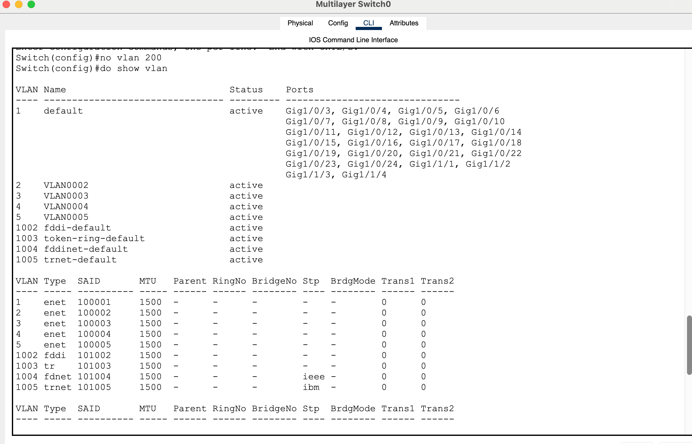
To restore the VLAN database across the network, you need to trigger a new revision update. One simple way to do this is by making a small VLAN change:
no vlan 200
This forces the core switch to advertise a new revision using correct vtp configuration in cisco packet tracer.
Verifying Recovery
Once the update is pushed:
VLANs should reappear on access switches
Connectivity should return
Test it with a ping:
ping 10.0.30.30
If replies are successful, your network has fully recovered.
What This Lab Teaches You
This entire exercise shows that vtp configuration in cisco packet tracer is not just about saving time—it’s about understanding control and risk.
VTP can simplify your network, but it can also destroy it if handled incorrectly.
That’s why many real-world networks either secure VTP heavily or avoid it altogether.
Full Lab:
My Packet tracer lab:
Generate 4 PC’s 2 2960 layer 2 switches 2 3650 layer 3 switches (but only create one first)
Connect the 1st layer switch to the 2 layer 2 switches Connect interfaces g1/0/1 to g1/0/1. Connect interfaces g1/0/2 to g1/0/2. Use the place note icon to label the ports in the logical topology.
Power the layer switches with a power supply and let them boot up. Enter the config for the 1st switch, Multilayer Switch0. Enter global config mode. Switch>en Switch#conf t Configure the default gateway. Switch(config)#ip default-gateway 10.0.1.1
To enable inter vlan routing, enter command: ip routing. Switch(config)#ip routing Configure a vtp domain name by entering the following global command: Switch(config)#vtp domain havoc
Bring vlan 1 up from the administratively down state.
Assign an ip address. Switch(config-if)#ip address 10.0.1.1 255.255.255.0
Create interface vlans 2 – 5, assign them ip addresses and perform no shut just in case.
Switch(config-if)#exit Switch(config)#int vlan 2 Switch(config-if)# %LINK-5-CHANGED: Interface Vlan2, changed state to up Switch(config-if)#ip address 10.0.20.1 255.255.255.0 Switch(config-if)#no shut Switch(config-if)#exit Switch(config)#int vlan 3 Switch(config-if)# %LINK-5-CHANGED: Interface Vlan3, changed state to up Switch(config-if)#ip address 10.0.30.1 255.255.255.0 Switch(config-if)#no shut Switch(config-if)#exit Switch(config)#int vlan 4 Switch(config-if)# %LINK-5-CHANGED: Interface Vlan4, changed state to up Switch(config-if)#ip address 10.0.40.1 255.255.255.0 Switch(config-if)#no shut Switch(config-if)#exit Switch(config)#int vlan 5 Switch(config-if)# %LINK-5-CHANGED: Interface Vlan5, changed state to up Switch(config-if)#ip address 10.0.50.1 255.255.255.0 Switch(config-if)#no shut Switch(config-if)#end Switch# %SYS-5-CONFIG_I: Configured from console by console Switch#show vlan
Configure g1/0/1 and g1/0/2 switchport modes as trunk to bring the vlan protocols up.
Switch(config)#int g1/0/1
Switch(config-if)#switchport mode trunk Switch(config-if)# %LINEPROTO-5-UPDOWN: Line protocol on Interface GigabitEthernet1/0/1, changed state to down %LINEPROTO-5-UPDOWN: Line protocol on Interface GigabitEthernet1/0/1, changed state to up %LINEPROTO-5-UPDOWN: Line protocol on Interface Vlan2, changed state to up %LINEPROTO-5-UPDOWN: Line protocol on Interface Vlan3, changed state to up %LINEPROTO-5-UPDOWN: Line protocol on Interface Vlan4, changed state to up %LINEPROTO-5-UPDOWN: Line protocol on Interface Vlan5, changed state to up Switch(config-if)#exit Switch(config)#int g1/0/2 Switch(config-if)#switchport mode trunk Switch(config-if)# %LINEPROTO-5-UPDOWN: Line protocol on Interface GigabitEthernet1/0/2, changed state to down %LINEPROTO-5-UPDOWN: Line protocol on Interface GigabitEthernet1/0/2, changed state to up
Switch(config-if)#end
Verify that the interfaces and protocols are up.
Switch#sho ip int bri
On both access switches, configure f0/1 and f0/2 as access ports.
Switch>en Switch#conf t Enter configuration commands, one per line. End with CNTL/Z. Switch(config)#int f0/1 Switch(config-if)#switchport mode access Switch(config-if)#exit Switch(config)#int f0/2 Switch(config-if)#switchport mode access
Set both access layer switches to be vtp clients.
Switch(config)#vtp mode client
Verify that vlans have carried over the trunk link on both switches.
Switch#show vlan
For the pcs:
Configure ip addresses as:
PC 0 in VLAN 2: 10.0.20.20 PC 1 in VLAN 3: 10.0.30.30 PC 2 in VLAN 4: 10.0.40.40 PC 3 in VLAN 5: 10.0.50.50
Configure management ip address on access switches for vlan 1.
10.0.1.2 10.0.1.3
Configure vlan the 1 ip address of the core switch as the default gateway on the access layer switches.
Save all running configurations of switches to the start up config.
Copy run start
Reboot the switches:
Reload
Create a new layer 3 switch after the model 3650. Generate a higher vtp revision number than the original layer 3 core switch. Save the config.
Configure g1/0/1 interface with switchport trunking and validate the change.
Switch(config)#int g1/0/1 Switch(config-if)#switchport mode trunk Switch(config-if)#do sho int g1/0/1 switchport
Copy run start
Reload the switch.
Connect this switch to the original switch on port g1/0/3.
This will wipe out your vlans.
Essentially a vlan hopping vtp attack causing a DOS (Denial of Service) attack on configured vlans.
How can we recover and fix this??
Disconnect the end layer 3 switch that caused the vtp attack. Reload the original layer 3. Configure vtp mode on this switch to be server. Make another revision so that access layer switches acting as the vtp clients receive the subset advertisement.
For example: no vlan 200
This will update to vtp clients to remove this vlan and gain information about vlan 2 – 5 thus restoring campus configuration for vlans.
Test this by pinging a pc across the network.
For example:
PC 1:
C:>ping 10.0.30.30 Pinging 10.0.30.30 with 32 bytes of data: Request timed out. Reply from 10.0.30.30: bytes=32 time<1ms TTL=127 Reply from 10.0.30.30: bytes=32 time<1ms TTL=127 Reply from 10.0.30.30: bytes=32 time<1ms TTL=127
Packet Tracer Speed and Duplex Not Working: A Practical Lesson for CCNA Students
When studying for the CCNA, many learners attempt to simulate real-world networking issues inside Cisco Packet Tracer. One common area of confusion is packet tracer speed and duplex not working as expected during labs involving duplex mismatches, speed mismatches, and collisions.
This lesson explains what happens when testing speed and duplex in Packet Tracer, why the results differ from real-world networks, and what students should focus on instead. Previously, we saw how Packet Tracer limited us from forwarding local broadcasts on a router.
Understanding the Goal of Speed and Duplex Labs
In real networking environments, configuring speed and duplex settings incorrectly can lead to serious issues such as:
Late collisions
CRC errors
Frame retransmissions
Poor network performance
A typical lab attempts to recreate these problems by:
Forcing one side to half duplex
Leaving the other side on auto
Generating heavy traffic using extended ping
However, when performing these steps in Packet Tracer, students quickly notice that packet tracer speed and duplex not working realistically becomes a major limitation.
Lab Topology and Basic Requirements
A example test topology can consist of the following:
Router → Switch → PC
Before testing connectivity, it is important to remember:
A router or switch cannot successfully send pings unless the interface is configured with an IP address. For a layer 2 switch, we would have to configure a VLAN and assign it an ip address and subnet mask. The ping command uses the ICMP protocol at layer 3 and requires a source ip address to ping a destination ip address.
When using extended ping:
Pressing Enter at the protocol prompt defaults to IP
Packet Tracer may behave inconsistently with large datagram sizes
Very high repeat counts can produce unstable or unrealistic results
These early observations already hint at packet tracer speed and duplex not working exactly like real equipment.
Extended Ping Behavior in Packet Tracer
Extended ping is often used to simulate heavy traffic. In real networks, increasing packet size and repeat count should stress the link.
In Packet Tracer:
Datagram sizes around 15000 bytes may behave unpredictably
A slightly smaller size, such as 14000 bytes, may work more consistently
Very high repeat counts (e.g., 1000) do not truly simulate sustained congestion
This shows that traffic generation itself is limited, contributing to the broader issue of packet tracer speed and duplex not working under stress conditions.
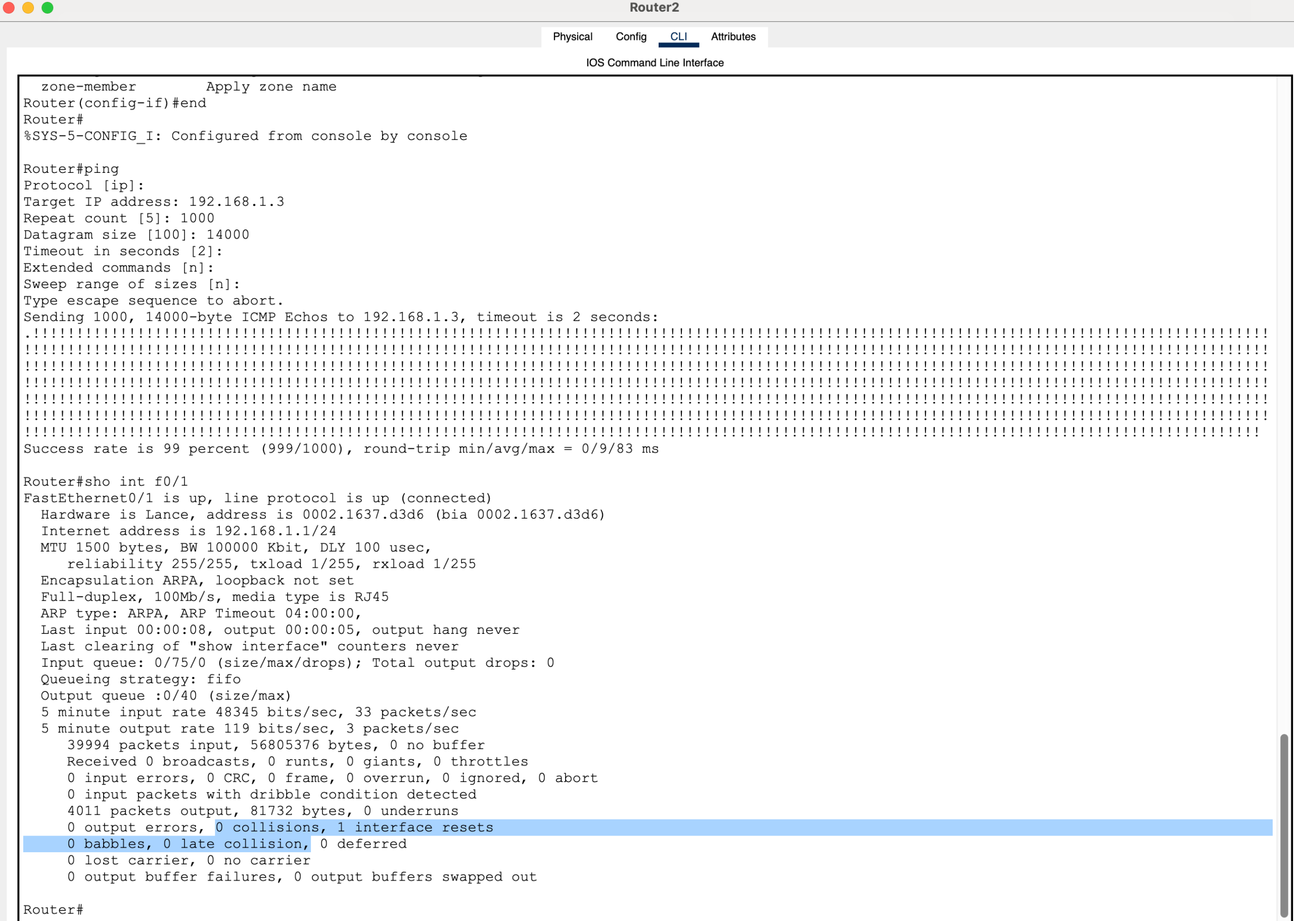
Here is an example of how to exact the “extended ping” command in user privileged mode:
ping Protocol [ip]: Target IP address: 192.168.1.3 Repeat count [5]: 1000 Datagram size [100]: 14000 Timeout in seconds [2]: Extended commands [n]: Sweep range of sizes [n]:
Duplex Mismatch Testing
Typical Configuration:
One side: half duplex
Other side: auto negotiation
Expected Real-World Outcome:
Late collisions (on the half-duplex side)
CRC errors
Significant performance degradation
Packet Tracer Result:
No collisions
No visible errors
Normal performance
This demonstrates a key limitation: packet tracer speed and duplex not working when attempting to reproduce duplex mismatch symptoms.
Router-to-Router Duplex Testing
When testing directly between two routers:
One router set to half duplex
The other set to auto
Large packet sizes and high repeat counts used
For example:
Router>en Router#conf t Router(config)#int f0/1 Router(config-if)#duplex half
Result:
Stable connectivity
No collision indicators
No performance issues
If you enter command “show interface” for the particular interface number on the router, you will see Full-duplex is listed even if you use the command “duplex half” to set half duplex on the router.
To further validate this, you can enter the command in exec privledged mode “show running configuration” which reveal that the “duplex half” command is configured to the interface.
Note: The “clear counters” does not exist as a command on Cisco iOS in packet tracer. Switching to simulation mode proves that nothing is breaking on the local link segment. Analyzing the PDUs as they traverse the link shows normal behavior when it should not be.
In a real network, this scenario would produce clear signs of a duplex mismatch. In Packet Tracer, however, packet tracer speed and duplex not working continues to prevent realistic outcomes.
Speed Mismatch Testing
Various configurations can be tested:
One side set to 10 Mbps, the other set to auto
One side forced to 100 Mbps, the other mismatched
Interfaces shut and re-enabled during testing
For example:
Router>en Router#conf t Enter configuration commands, one per line. End with CNTL/Z. Router(config)#int f0/1 Router(config-if)#speed 10
Expected Real-World Behavior:
Auto-negotiation fallback to half duplex
Duplex mismatches
Performance issues and collisions
Packet Tracer Behavior:
The link either works perfectly
Or the link goes down entirely
There is little to no “degraded performance” state. This reinforces the conclusion that packet tracer speed and duplex not working eliminates the subtle failures seen in real networks.
Testing with a Hub (Collision Domain)
A hub introduces a shared collision domain, making it ideal for testing collisions.
Topology:
Router → Hub → End Device
Expected Behavior:
Frequent collisions under load
Late collisions
Packet loss patterns
Packet Tracer Result:
Partial ping success (e.g., ~90%)
No late collisions
No meaningful error feedback
Even in a scenario designed to produce collisions, packet tracer speed and duplex not working prevents accurate simulation.
Why Packet Tracer Does Not Behave Like Real Networks
Packet Tracer is designed as a learning tool focused on configuration and logical behavior, not physical-layer accuracy.
It does NOT fully simulate:
CSMA/CD collision detection
Timing-based collisions
Interface buffering and congestion
Real hardware error counters
Because of this, packet tracer speed and duplex not working is not a bug—it is a limitation of the simulator.
What Would Happen on Real Equipment
On real hardware or advanced emulators, the same tests would produce:
Late collisions (especially on half-duplex interfaces)
CRC and input errors
Retransmissions
Noticeable performance degradation
Increasing interface error counters
These are critical troubleshooting signals that are largely absent when packet tracer speed and duplex not working in a realistic manner.
Key CCNA Concepts to Remember
Even though Packet Tracer does not display these behaviors, the exam expects full understanding of the theory:
Duplex mismatch occurs when one side is full duplex and the other is half duplex
This results in collisions and poor performance
Collisions only occur in half-duplex environments
Auto-negotiation failures are a common cause of mismatches
Students should not rely on Packet Tracer to validate these symptoms, especially when packet tracer speed and duplex not working leads to misleading lab results.
Final Lesson Summary
When performing speed and duplex labs:
Expect Packet Tracer to behave differently from real networks
Do not rely on it to demonstrate collisions or error conditions
Focus on understanding configuration and theory
Recognize that packet tracer speed and duplex not working is a known limitation
Packet Tracer remains an excellent tool for learning commands and topology design. However, for realistic behavior involving collisions and duplex mismatches, more advanced tools or real hardware are required.
Packet Tracer Forward Broadcast Messages on a Router Example
Table of Contents
If you’ve been trying to figure out how to packet tracer forward broadcast messages on a router example, you’ve probably hit a wall.
You type the command. You follow the textbook. And then… nothing works.
That’s not your fault.
There’s a hidden limitation inside Cisco Packet Tracer that almost nobody explains clearly — and it’s exactly why your lab keeps failing.
So instead of wasting hours trying commands that don’t exist, let’s walk through a real, working example that demonstrates the concept of forwarding broadcast messages on a router inside Packet Tracer.
This is the version that actually works — and more importantly, the version that helps you understand what’s really going on.
Why Forwarding Broadcast Messages Is Confusing in Packet Tracer
In real Cisco networking, routers can forward broadcast traffic under certain conditions.
But here’s the catch:
By default, routers do not forward broadcasts. This is intentional. It prevents things like broadcast storms and amplification attacks.
There is a feature called directed broadcast, which allows forwarding packets sent to addresses like:
192.168.1.255
The biggest issue with any packet tracer forward broadcast messages on a router example is that the expected behavior differs from real Cisco IOS.
So when you try to configure:
ip directed-broadcast
You’ll notice something frustrating:
The command either doesn’t exist… or does nothing.
That’s the moment where most people think they’re doing something wrong.
But you’re not.
This is exactly why many learners struggle to complete a working packet tracer forward broadcast messages on a router example in their labs.
To build a working packet tracer forward broadcast messages on a router example, we need to use a method that Packet Tracer actually supports.
The Working Approach: Using DHCP Relay (ip helper-address)
If you want a packet tracer forward broadcast messages on a router example that actually works, you need to use a different mechanism:
DHCP relay via ip helper-address
This may be the only reliable way in Packet Tracer to simulate a router forwarding broadcast traffic.
Here’s why:
A DHCP request is a broadcast packet. The router receives it and then forwards it as a unicast packet to another network.
That transformation is the key.
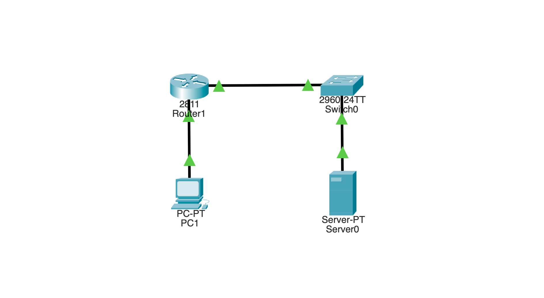
The Lab Topology
You only need four devices:
One PC (client)
One router
One switch
One server (DHCP server)
The layout looks like this:
PC1 ---- Router ---- Switch ---- Server
You’ll create two networks:
10.0.0.0/24 → where the broadcast starts
192.168.1.0/24 → where the server lives
Step 1: Configure the Router Interfaces
Start by setting up the router so it connects both networks.
enable
configure terminalinterface g0/0
 ip address 10.0.0.1 255.255.255.0
 no shutdowninterface g0/1
 ip address 192.168.1.1 255.255.255.0
 no shutdown
Now the router knows both networks.
Step 2: Enable Broadcast Forwarding Behavior
Here’s the key part of this packet tracer forward broadcast messages on a router example.
On the interface connected to the PC network:
interface g0/0
 ip helper-address 192.168.1.10
This tells the router:
“If you see a broadcast here, forward it to that server.”
That’s the entire magic.
Step 3: Configure the Server
On the server:
IP address: 192.168.1.10
Subnet mask: 255.255.255.0
Default gateway: 192.168.1.1
Then go to:
Services → DHCP
Create a pool:
Network: 10.0.0.0
Default gateway: 10.0.0.1
Start IP: 10.0.0.100
Subnet mask: 255.255.255.0
Turn the DHCP service ON.
Step 4: Trigger the Broadcast
Now go to PC1:
Desktop → IP Configuration
Click DHCP
At this exact moment, PC1 sends a broadcast packet:
255.255.255.255
What Happens Behind the Scenes
This is where everything clicks.
The router receives the broadcast and checks:
Do I have a destination ip address configured for UDP?
Yes.
So instead of forwarding the broadcast, it:
Drops the broadcast packet
Converts it into a unicast packet
Sends it to 192.168.1.10
The server responds, and the process completes.
Even if you don’t care about the IP assignment, what matters is this:
👉 The router forwarded a broadcast-triggered message across networks
How to Visually Confirm It (The “Aha” Moment)
Switch Packet Tracer into Simulation Mode.
Now repeat the DHCP relay.
Watch closely:
You’ll see a broadcast leave PC1
The router receives it
Then a new packet leaves the router toward the server
PC1 will receive an Apippa address since it will not receive a response from the server on the 192.168.1.0 network.
That transformation is exactly what you were trying to prove.
Why Ping Doesn’t Work for This
Many people try:
ping 255.255.255.255
Or:
ping 192.168.1.255
And expect it to cross the router.
It won’t.
Here’s why:
Ping uses ICMP, not UDP
ip helper-address only forwards UDP unicasts.
Directed broadcast (needed for .255) isn’t supported in Packet Tracer
So the router simply drops it.
The Big Takeaway
If you’re searching for a packet tracer forward broadcast messages on a router example, here’s the truth:
You are not actually forwarding a broadcast directly.
You are:
Intercepting a broadcast
Dropping the broadcast.
Converting it into unicast
Forwarding it to another network
And that’s exactly what Cisco expects you to understand for CCNA.
Final Thoughts
It’s easy to get stuck thinking Packet Tracer is broken or that you’re missing something.
But once you understand the limitation, everything makes sense.
You’re not doing it wrong.
You just needed the right example.
And now you’ve got one that works, one that you can see in simulation, and one that actually teaches the concept behind forwarding broadcast messages on a router.
This simple topology is perfect for demonstrating a packet tracer forward broadcast messages on a router example without unnecessary complexity.
Cisco Packet Tracer provides two different ways to view and build networks: Logical Mode and Physical Mode. Logical mode focuses on device connectivity and configuration, while physical mode allows you to organize network infrastructure into realistic environments such as buildings, wiring closets, and server racks.
In this project we will gradually build a small enterprise-style network while learning how physical and logical views work together.
This lab will evolve over time as new components are added.
Lab Overview
In this Packet Tracer project we will build a small enterprise network containing:
• Cable modem representing the WAN • Cisco 4331 router acting as the gateway • Cisco 3650 multilayer switch • VLAN segmentation • DHCP services • DNS server • Inter-VLAN routing • Configuration backups
Network VLAN layout:
VLAN
Purpose
Subnet
10
Office Network
10.0.10.0/24
20
Guest Network
10.0.20.0/24
30
Voice Network
10.0.30.0/24
80
Management Network
10.0.80.0/24
Lab 1 — Understanding Physical Mode in Packet Tracer
Open a new file in Packet Tracer.
On the third menu from the top, click the Physical option to enter the physical view.
To adjust the environment view:
• Click the minus (-) button to zoom all the way out • Click the plus (+) button to zoom in
This allows you to see the entire simulated physical environment.
Customizing the Physical Background
Packet Tracer allows you to customize the physical environment using background images.
You can:
• Draw your own images in design software • Generate images using AI tools • Download images online
Be aware that you may need permission to use certain images depending on copyright restrictions.
To change the background image:
Click the Set Background Image icon on the third menu bar
The icon is located next to the wireless symbol
Click Browse
Select the background image
Click Apply
Click X to close the window
Organizing Physical Locations
Physical mode allows you to organize regions of your simulated network environment.
Examples include:
• State • City • Inner city • Buildings • Offices • Wiring closets
This provides a more realistic approach when building network topologies.
Your logical and physical views correspond, so you always know where devices are located both physically and logically.
Naming Physical Locations
To rename physical views:
Navigate to the Navigation Panel icon.
To the left of the icon is a text input field where you can rename the location.
You can navigate through physical locations by:
• Left-clicking or right-clicking the location • Clicking the Back Level icon • Using keyboard shortcuts
Windows ALT + Left Arrow
Mac Option + Left Arrow
Navigate through the hierarchy until you reach the main wiring closet.
Lab 2 — Installing Network Infrastructure
Once inside the wiring closet, navigate to the bottom device menu.
Click the Network Devices icon.
Add the Cable Modem
Select WAN Emulation (cloud icon).
Drag the Cable Modem onto the wall.
Install the Router
Click Routers.
Drag the Cisco 4331 router underneath the Power Distribution device in the rack.
Right-click the router and select:
Inspect Rear
Turn the router off.
Install the following modules:
NIM-ES2-4 (two modules)
Each module provides four Gigabit Ethernet switching ports.
Turn the router back on.
Lab 3 — Rack Equipment Layout
Click Connections.
Select Structured Cabling.
Drag the Copper Patch Panel into the rack under the router while leaving space for the switch.
In Packet Tracer this is cosmetic only, but in real networks patch panels are used for professional cable management.
Lab 4 — Installing the Layer 3 Switch
Navigate to:
Network Devices → Switches
Drag the 3650-24PS multilayer switch into the rack between the router and the copper patch panel.
Open the switch configuration window.
Install the following modules:
• 4 × GLC-TE Cisco 1000BASE-T SFP modules • AC Power Supply • Power Cover Plate (optional)
Lab 5 — Connecting the Core Network
Click Connections.
Create the following links using copper straight-through cables.
Drag a Server into the rack under the copper patch panel.
Configure the Server Interface
Navigate to:
Config → FastEthernet0
Disable automatic negotiation by unchecking:
• Auto Link Speed • Auto Duplex
Configure Server IP Address
Navigate to:
Desktop → IP Configuration
Set the configuration to Static.
IP Address 10.0.80.3
Subnet Mask 255.255.255.0
Default Gateway 10.0.80.1
DNS Server 10.0.80.3
Enable DNS Service
Navigate to:
Services → DNS
Turn the DNS service ON.
Create a DNS record:
server.local → 10.0.80.3
Connect the Server
Connect:
Server FastEthernet0 → Switch GigabitEthernet1/0/3
Use a copper straight-through cable.
Lab 7 — Out-of-Band Switch Management
Drag a Laptop to the table.
Click Connections.
Select the Console cable.
Connect:
Laptop RS-232 → Switch Console Port
This allows Out-of-Band Management, meaning the device can be managed even if the network is not operational.
Lab 8 — Basic Switch Configuration
Open the laptop.
Navigate to:
Desktop → Terminal
When prompted:
Would you like to enter the initial configuration dialog?
Enter:
no
Enter Privileged Mode
en
Enter Configuration Mode
conf t
Rename the Switch
hostname MainSwitch
Save the Configuration
do copy run start
Press Enter when prompted.
Lab 9 — Secure Privileged Mode
enable algorithm-type scrypt secret what ya gonna do brother
This protects privileged EXEC mode using a Type-9 scrypt hash.
Lab 10 — Enable Discovery Protocols
cdp run
lldp run
LLDP allows discovery with non-Cisco equipment such as Juniper, HP, Ubiquiti, and Linux systems.
Lab 11 — Configure the Routed Uplink
interface gigabitethernet1/0/1
description Uplink to router gateway
no switchport
ip address 10.0.0.2 255.255.255.0
ip route 0.0.0.0 0.0.0.0 10.0.0.1
duplex full
speed 100
exit
This converts the switch port into a Layer 3 routed interface.
Lab 12 — Creating VLAN Interfaces
VLAN 10 — Office
interface vlan 10
ip address 10.0.10.1 255.255.255.0
description Office
VLAN 20 — Guest
interface vlan 20
ip address 10.0.20.1 255.255.255.0
description Guest
VLAN 30 — Voice
interface vlan 30
ip address 10.0.30.1 255.255.255.0
description Voice
VLAN 80 — Management
interface vlan 80
ip address 10.0.80.1 255.255.255.0
description Management
Lab 13 — DHCP Configuration
Management VLAN
ip dhcp excluded-address 10.0.80.1 10.0.80.3
ip dhcp pool 10.0.80.0_Clients
network 10.0.80.0 255.255.255.0
default-router 10.0.80.1
dns-server 10.0.80.3
Office VLAN
ip dhcp excluded-address 10.0.10.1
ip dhcp pool 10.0.10.0_Clients
network 10.0.10.0 255.255.255.0
default-router 10.0.10.1
dns-server 10.0.80.3
Guest VLAN
ip dhcp excluded-address 10.0.20.1
ip dhcp pool 10.0.20.0_Clients
network 10.0.20.0 255.255.255.0
default-router 10.0.20.1
dns-server 10.0.80.3
Voice VLAN
ip dhcp excluded-address 10.0.30.1
ip dhcp pool 10.0.30.0_Clients
network 10.0.30.0 255.255.255.0
default-router 10.0.30.1
dns-server 10.0.80.3
Lab 14 — Enable Inter-VLAN Routing
ip routing
This allows the multilayer switch to route traffic between VLAN networks.