Configure DTP in Packet Tracer Table of Contents
Configure DTP Packet Tracer:
Learning how to configure DTP Packet Tracer environments properly is one of the most underrated skills you can develop. Most people rush through trunking concepts, memorize a few commands, and move on. But if you truly take the time to configure DTP Packet Tracer labs in depth, you begin to understand how switches actually communicate, negotiate, and sometimes fail.
This guide is designed to go beyond surface-level explanations. You’re not just going to configure DTP Packet Tracer once and call it a day. Instead, you’ll repeatedly configure DTP Packet Tracer across multiple interfaces, explore different combinations, intentionally break things, and fix them again. That repetition is what builds real understanding.
By the time you finish, the phrase configure DTP Packet Tracer won’t just be a concept—it’ll represent a skill you actually own.

Why You Should Learn to Configure DTP Packet Tracer the Right Way
Previously, we wrote about VTP, how to break it and how to fix it.
When you first hear about trunking, it seems simple. You connect two switches, enable trunking, and VLANs pass through. But once you begin to configure DTP Packet Tracer labs, you realize that trunking is not just a switch you turn on or off. It’s a negotiation process.
DTP controls whether a port becomes a trunk or stays an access port. And when you configure DTP Packet Tracer environments with different modes on each side, the outcome depends entirely on how those modes interact.
This is why repeatedly practicing how to configure DTP Packet Tracer is so important. You’re training yourself to think like a switch. You’re learning how it decides, how it responds, and how it behaves when configurations don’t align.
Lab Setup: Preparing to Configure DTP Packet Tracer
Before you begin to configure DTP Packet Tracer, you need a topology that allows you to test multiple scenarios at once.
Start by adding:
- One router (2901)
- Two switches (3650)
Connect the router to Switch1. Then connect Switch1 to Switch2 using multiple links, such as interfaces g1/0/2 through g1/0/9.
This setup allows you to configure DTP Packet Tracer across several ports simultaneously, which is critical for observing different behaviors side by side.
From your notes, all ports begin as access ports using dynamic auto behavior . This is the perfect baseline when you configure DTP Packet Tracer because it reflects how switches behave by default.
Understanding the Modes Before You Configure DTP Packet Tracer
Before you configure DTP Packet Tracer links, you need to understand the modes you’ll be working with.
Dynamic auto is passive. It waits. It does nothing unless the other side initiates trunking.
Dynamic desirable is active. It tries to form a trunk immediately.
Static trunk forces trunking regardless of negotiation.
Nonegotiate disables DTP entirely.
When you configure DTP Packet Tracer, you’re really testing how these modes interact with each other. That interaction determines everything.

First Scenario: Auto Meets Desirable
To begin, configure DTP Packet Tracer on interface g1/0/3.
Set Switch2 to dynamic desirable while Switch1 remains dynamic auto.
As soon as you configure DTP Packet Tracer this way, the desirable side initiates trunking and the auto side accepts. The result is a trunk.
This is one of the most important combinations when you configure DTP Packet Tracer because it demonstrates how negotiation actually works.
When you verify the interface, you’ll see that the operational mode becomes trunk. This confirms that your attempt to configure DTP Packet Tracer was successful.
Second Scenario: Desirable Meets Desirable
Now configure DTP Packet Tracer on both sides of another interface, such as g1/0/4, using dynamic desirable.
When you configure DTP Packet Tracer this way, both sides actively try to form a trunk. There is no waiting. The trunk forms immediately.
This scenario reinforces a key idea. When you configure DTP Packet Tracer, the behavior is not determined by one side alone. Both sides matter.
Third Scenario: Static Trunk with No Negotiation
Next, configure DTP Packet Tracer using static trunk mode combined with nonegotiate.
When you configure DTP Packet Tracer like this, the link becomes a trunk without any negotiation at all.
This is how trunking is often configured in real networks. Instead of relying on DTP, administrators manually define trunk ports for better security.
Even though you are still practicing how to configure DTP Packet Tracer, this step teaches you what happens when DTP is removed from the equation entirely.
Fourth Scenario: Mixed Configurations
Now things get more interesting.
Configure DTP Packet Tracer so that one side is dynamic desirable and the other side is a static trunk with no negotiation.
The trunk still forms. Why? Because the static trunk forces the link into trunk mode.
But now reverse the situation.
Configure DTP Packet Tracer so that one side is dynamic auto and the other side is nonegotiate. Suddenly, nothing happens. No trunk forms.
This is one of the most important lessons you’ll learn when you configure DTP Packet Tracer. Not all mismatches are obvious. Some quietly fail.
Extending VLANs After You Configure DTP Packet Tracer
Once you successfully configure DTP Packet Tracer and form trunk links, the next step is to pass VLAN traffic across them.
Create VLAN 2 and enable it. Then allow VLAN 2 on your trunk ports.
At this point, your efforts to configure DTP Packet Tracer begin to pay off. The trunks you created now serve a real purpose—carrying VLAN traffic.
Breaking the Network After You Configure DTP Packet Tracer
To truly understand what you’ve done, you need to break it.
Take one of your trunk ports and reconfigure it as an access port in VLAN 2.
Now the link is mismatched. One side thinks it’s a trunk. The other side thinks it’s an access port.
When you configure DTP Packet Tracer incorrectly like this, the network begins to behave unpredictably. Spanning tree may react. Traffic paths may change.
From your notes, traffic can still traverse unexpected paths when trunks are broken . This is exactly what you want to observe.
Observing Traffic Flow
Switch to simulation mode and send traffic across the network.
Because you took the time to configure DTP Packet Tracer and then break it, you can now observe how the network adapts.
This is where the learning becomes real. You’re no longer just configuring—you’re analyzing behavior.
Fixing the Network
Now restore the trunk.
Reconfigure the broken port using dynamic desirable and allow VLAN 2.
As soon as you configure DTP Packet Tracer correctly again, the trunk reforms. The mismatch disappears. The network stabilizes.
This reinforces a powerful concept. When you configure DTP Packet Tracer properly, the network behaves predictably. When you don’t, it doesn’t.
Repetition Builds Mastery
At this point, you should repeat the process.
Configure DTP Packet Tracer on different ports using different combinations. Observe the results. Break things again. Fix them again.
The more you configure DTP Packet Tracer, the more natural it becomes.
Real-World Perspective
In production environments, many engineers disable DTP entirely and use static trunking. This reduces risk and improves security.
However, even if you don’t use DTP in real networks, understanding how to configure DTP Packet Tracer is still critical. Because you will encounter it. And when you do, you need to understand how it works.

Final Thoughts
Learning how to configure DTP Packet Tracer is not about memorizing commands. It’s about understanding behavior.
Every time you configure DTP Packet Tracer, you’re training yourself to think like a network device. You’re learning how switches negotiate, how they fail, and how they recover.
And that understanding is what separates beginners from professionals.
So don’t just configure DTP Packet Tracer once. Do it again. Test new combinations. Break things intentionally. Fix them confidently.
Because the more you configure DTP Packet Tracer, the more everything else in networking starts to make sense.
Follow along lab:
In packet tracer:
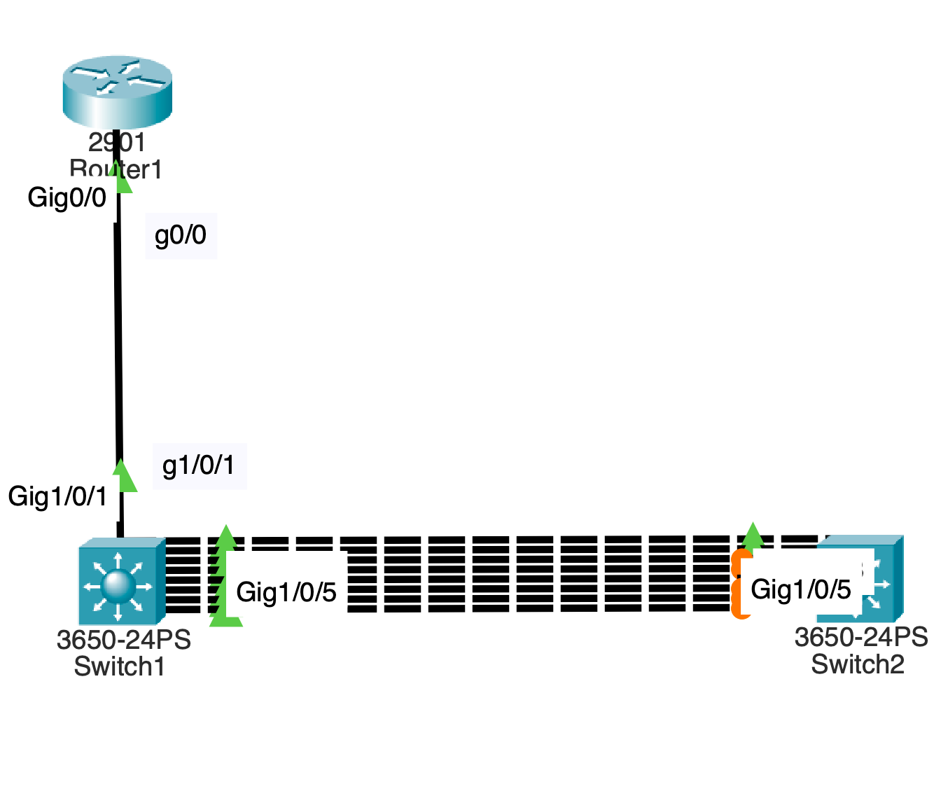
Drag a router 2901 into the logical topology.
Drag 2 3650 switches into logical topology.
Name them Router1 which is in front of switch1 and switch2.
Connect g1/0/1 to g0/0 from switch1 to router using a straight through cable.
Connect switch2 to switch1 using a crossover cable.
Connect g1/0/2 to g1/0/2
Do the same for g1/0/3 ,4, 5, 6, 7, 8 and 9.
You should have 4 connections between both switches.
In terms of DTP all physical swichports are configured to be static access ports with dynamic auto configured.
Leave port g1/0/2 as is on both sides of the connection.
Configure port g1/0/3 as dynamic desirable on switch 2..
Commands:
En
Conf t
Int g1/0/3
Switchport mode dynami des
End
This creates a trunk on the link.
Validate the following updates:
Administrative Mode: dynamic desirable
Operational Mode: trunk
Administrative Trunking Encapsulation: dot1q
Operational Trunking Encapsulation: dot1q
Negotiation of Trunking: On
Access Mode VLAN: 1 (default)
Commands:
sho interfaces g1/0/3 switchport
Go to switch1 and run the same command.
Validate the following updates:
Administrative Mode: dynamic auto
Operational Mode: trunk
Administrative Trunking Encapsulation: dot1q
Operational Trunking Encapsulation: dot1q
Negotiation of Trunking: On
On both switches, configure dynamic desirable for g1/0/4 ports.
Commands:
Switch#conf t
Switch(config)#int g1/0/4
Switch(config-if)#switchport mode dynamic desirable
end
This will create a trunk.
Check for updates on switch1 on the port.
Commands:
sho interfaces g1/0/4 switchport
For switch2 and switch1, Validate the following updates:
Administrative Mode: dynamic desirable
Operational Mode: trunk
Administrative Trunking Encapsulation: dot1q
Operational Trunking Encapsulation: dot1q
Negotiation of Trunking: On
Configure both sides of the link for ports g1/0/5 to be static trunk ports with no negotiation.
This will create a trunk port.
Commands:
Switch#conf t
Switch(config)#int g1/0/5
Switch(config-if)#switchport mode trunk
Switch(config-if)#switchport nonegotiate
Switch(config-if)#end
Switch#
Check for updates on the switchport.
Commands:
Switch#sho interfaces g1/0/5 switchport
Validate the updates for the switchport:
Administrative Mode: trunk
Operational Mode: trunk
Administrative Trunking Encapsulation: dot1q
Operational Trunking Encapsulation: dot1q
Negotiation of Trunking: Off
On switch1, configure port g1/0/6 to be dynamic desirable
Commands:
En
Conf t
Int g1/0/6
Switchport mode dynami des
End
Commands:
sho interfaces g1/0/6 switchport
Validate the following:
Administrative Mode: dynamic desirable
Operational Mode: trunk
Administrative Trunking Encapsulation: dot1q
Operational Trunking Encapsulation: dot1q
Negotiation of Trunking: On
On switch2, configure g1/0/6 as a static trunk with no negotiation.
en
conf t
int g1/0/6
switchport mode trunk
switchport nonegotiate
end
Validate the updates for port g1/0/6
Commands:
sho interfaces g1/0/6 switchport
Administrative Mode: trunk
Operational Mode: trunk
Administrative Trunking Encapsulation: dot1q
Operational Trunking Encapsulation: dot1q
Negotiation of Trunking: Off
On port g1/0/7 configure dynamic desirable on both sides of the link.
Commands:
en
conf t
int g1/0/7
switchport mode dynam des
End
Validate the updates for port g1/0/7
Commands:
sho interfaces g1/0/7 switchport
Switchport: Enabled
Administrative Mode: dynamic desirable
Operational Mode: trunk
Administrative Trunking Encapsulation: dot1q
Operational Trunking Encapsulation: dot1q
Negotiation of Trunking: On
On switch1, configure g1/0/8 as a static trunk with no negotiation.
Commands:
en
conf t
int g1/0/8
switchport mode trunk
switchport nonegotiate
End
Check for updates on the switch port and validate them:
Commands:
sho interfaces g1/0/8 switchport
Administrative Mode: trunk
Operational Mode: trunk
Administrative Trunking Encapsulation: dot1q
Operational Trunking Encapsulation: dot1q
Negotiation of Trunking: Off
On switch2, leave access port as is.
Check for updates on the switch port and validate them:
Commands:
sho interfaces g1/0/8 switchport
Administrative Mode: dynamic auto
Operational Mode: static access
Administrative Trunking Encapsulation: dot1q
Operational Trunking Encapsulation: native
Negotiation of Trunking: On
Notices that operating as an access port.
On switch1, enable vlan 2.
Commands:
conf t
int vlan 2
no shut
Add vlan to trunk ports.
Commands:
interface range g1/0/3, g1/0/4, g1/0/5, g1/0/6, g1/0/7, g1/0/8,
switchport trunk allowed vlan 2
Configure switchport g1/0/9 to be dynamic desirable.
Commands:
En
conf t
int g1/0/9
switchport mode dyn de
switchport trunk allowed vlan 2
Do the same on switch2.
Now break the trunk so that it becomes a Native VLAN mismatch.
Commands:
switchport mode access
switchport access vlan 2
On both switches, pull up spanning tree summary to see validate that 6 vlan ports are forwarding on switch2 while 3 ports are blocking on and 2 ports are forwarding on switch1 for vlan 2.
On Router1, configure an ip address on interface port g0/0.
Router>en
Router#conf t
Router(config)#int g0/0
Router(config-if)#ip ad
Router(config-if)#ip address 10.0.0.1 255.255.255.0
On switch1, configure an ip address on vlan 2 for management address.
Commands:
Switch#conf t
Switch(config)#int vlan 2
Switch(config-if)#ip address 10.0.0.2 255.255.255.0
Switch(config-if)#
Do the same on switch2.
Commands:
Switch>en
Switch#conf t
Switch(config)#int vlan 2
Switch(config-if)#ip address 10.0.0.3 255.255.255.0
Switch(config-if)#
Switch to simulation mode in packet tracer.
Go to router1 and ping 10.0.0.3.
Notice that the packet traverses along the g1/0/9 broken trunk link where vlan 2 is added to the static access port of g1/0/9 on switch2.
On switch2, change port g1/0/9 back to dynamic desirable.
Commands
Switch(config-if)#int g1/0/9
Switch(config-if)#swit
Switch(config-if)#switchport mode dya
Switch(config-if)#switchport mode dyn
Switch(config-if)#switchport mode dynamic de
Check updates:
show interfaces g1/0/9 switchport
Validate the following:
Administrative Mode: dynamic desirable
Operational Mode: static access
Administrative Trunking Encapsulation: dot1q
Operational Trunking Encapsulation: native
Negotiation of Trunking: On
Access Mode VLAN: 2 (VLAN0002)
Change the access port to a trunk port with vlan 2.
Commands:
Switch#conf t
Enter configuration commands, one per line. End with CNTL/Z.
Switch(config)#int g1/0/9
Switch(config-if)#switchport trunk allowed vlan 2
Switch(config-if)#
Progress through the simulation as icmp continues.
Validate the following:
Administrative Mode: dynamic desirable
Operational Mode: trunk
Administrative Trunking Encapsulation: dot1q
Operational Trunking Encapsulation: dot1q
Negotiation of Trunking: On
Access Mode VLAN: 2 (VLAN0002)
The error for Native VLAN mismatch will go away.