Table of Contents
VLAN Hopping VTP Attack and Recovery in a Campus Network (VTP Configuration In Cisco Packet Tracer)
If you are learning networking or working toward your CCNA, understanding vtp configuration in cisco packet tracer is essential. It’s one of those topics that seems simple at first—until you see how badly things can go wrong.
In a real network, a single mistake in vtp configuration in cisco packet tracer can wipe out every VLAN across multiple switches. That’s not just a misconfiguration—it’s a full-blown outage.
This lesson walks through a complete campus network lab where VLANs are built, broken, and restored. Along the way, you’ll see exactly how a VTP-based attack works and how proper vtp configuration in cisco packet tracer allows you to recover from it.
Why VTP Can Be Dangerous
VTP (VLAN Trunking Protocol) is designed to make VLAN management easier. Instead of configuring VLANs manually on every switch, you configure them once and let VTP distribute the information.
That’s where vtp configuration in cisco packet tracer becomes both powerful and risky.

VTP uses something called a revision number. Every time a VLAN change is made, the revision number increases. Switches trust the device with the highest revision number and accept its VLAN database as the truth.
Now imagine introducing a switch with a higher revision number—but no VLANs configured. That empty database gets pushed across the network, and suddenly everything is gone.
That’s the core idea behind this lab.
Building the Campus Network
To understand how vtp configuration in cisco packet tracer behaves in a real environment, you first need a structured topology.
This lab includes:
- A multilayer switch acting as the core
- Two access layer switches
- Four PCs across different VLANs
The setup follows a standard campus design where the core switch handles routing and VLAN management, while access switches rely on it.
The full configuration process is based on the lab steps towards the end of this post , which guide the entire topology build and recovery steps.
Configuring the Core Switch
The core switch is where your vtp configuration in cisco packet tracer begins.
First, enable Layer 3 functionality:
ip routing
Then define the VTP domain:
vtp domain havoc
Every switch that participates in vtp configuration in cisco packet tracer must share this domain name.
Next, configure VLAN interfaces with IP addresses so the switch can route traffic between them:
- VLAN 1 → 10.0.1.1
- VLAN 2 → 10.0.20.1
- VLAN 3 → 10.0.30.1
- VLAN 4 → 10.0.40.1
- VLAN 5 → 10.0.50.1
Bring each interface up, and now your core is ready to distribute VLAN information using vtp configuration in cisco packet tracer.
Enabling Trunk Links
VLAN information doesn’t magically move between switches—it travels over trunk links.
So part of proper vtp configuration in cisco packet tracer is enabling trunking:
interface g1/0/1
switchport mode trunkinterface g1/0/2
switchport mode trunk
Once trunking is active, VLAN advertisements begin flowing between switches.
Configuring Access Switches
Access switches rely entirely on the core for VLAN information when using vtp configuration in cisco packet tracer.
Set them to client mode:
vtp mode client
Now they will receive VLANs instead of creating them.
Configure access ports for end devices:
interface f0/1
switchport mode accessinterface f0/2
switchport mode access
Assign management IP addresses and a default gateway so the switches can be managed remotely.
At this point, your vtp configuration in cisco packet tracer is fully functional.
Assigning PCs to VLANs
Each PC is placed into a different VLAN:
- VLAN 2 → 10.0.20.20
- VLAN 3 → 10.0.30.30
- VLAN 4 → 10.0.40.40
- VLAN 5 → 10.0.50.50
Once configured, you should be able to ping between VLANs, confirming that your vtp configuration in cisco packet tracer and inter-VLAN routing are working correctly.
The Breaking Point: Simulating the Attack
Now that everything is working, it’s time to break it.
A new switch is introduced into the network, but this one has a higher VTP revision number. Its vtp configuration in cisco packet tracer is intentionally misaligned with the rest of the network.
After configuring trunking and connecting it to the core, something dramatic happens.
What Happens When VTP Goes Wrong
As soon as the rogue switch connects:
- It advertises its VLAN database
- Its higher revision number makes it authoritative
- The entire network accepts its configuration
If that database is empty, all VLANs disappear.
This is effectively a denial of service caused by improper vtp configuration in cisco packet tracer.
Suddenly:
- PCs lose connectivity
- VLANs vanish
- Routing stops working
Everything that was carefully built is gone in seconds.


Recovering the Network
Now comes the most important part—fixing the problem.
This is where understanding vtp configuration in cisco packet tracer really pays off.
First, disconnect the rogue switch. This stops the bad information from spreading.
Next, reload the core switch to reset its state.
Then reconfigure it as a VTP server:
vtp mode server
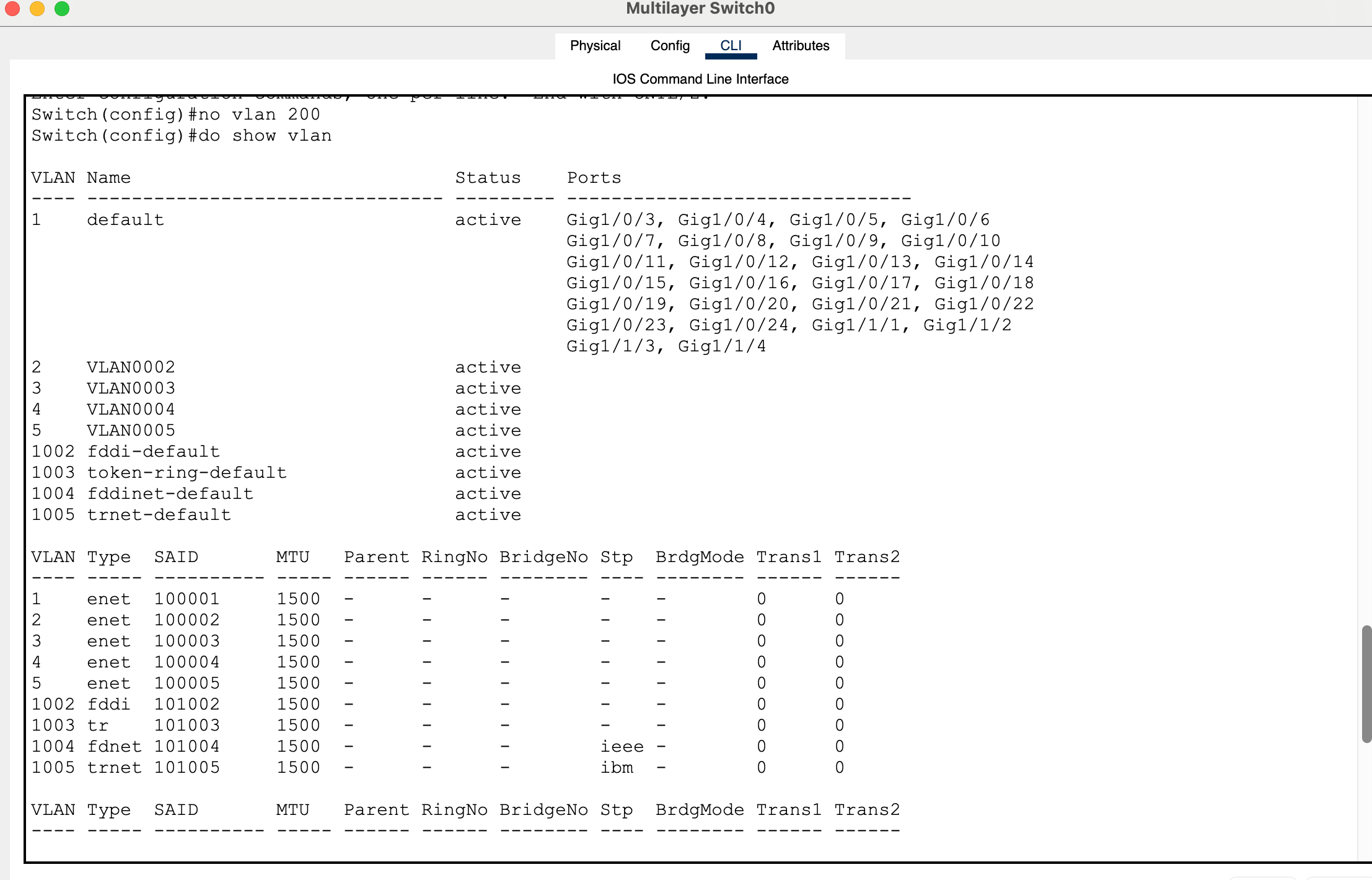
To restore the VLAN database across the network, you need to trigger a new revision update. One simple way to do this is by making a small VLAN change:
no vlan 200
This forces the core switch to advertise a new revision using correct vtp configuration in cisco packet tracer.
Verifying Recovery
Once the update is pushed:
- VLANs should reappear on access switches
- Connectivity should return
Test it with a ping:
ping 10.0.30.30
If replies are successful, your network has fully recovered.
What This Lab Teaches You
This entire exercise shows that vtp configuration in cisco packet tracer is not just about saving time—it’s about understanding control and risk.
VTP can simplify your network, but it can also destroy it if handled incorrectly.
That’s why many real-world networks either secure VTP heavily or avoid it altogether.
Full Lab:
My Packet tracer lab:
Generate 4 PC’s
2 2960 layer 2 switches
2 3650 layer 3 switches (but only create one first)
Connect the 1st layer switch to the 2 layer 2 switches
Connect interfaces g1/0/1 to g1/0/1.
Connect interfaces g1/0/2 to g1/0/2.
Use the place note icon to label the ports in the logical topology.
Power the layer switches with a power supply and let them boot up.
Enter the config for the 1st switch, Multilayer Switch0.
Enter global config mode.
Switch>en
Switch#conf t
Configure the default gateway.
Switch(config)#ip default-gateway 10.0.1.1
To enable inter vlan routing, enter command: ip routing.
Switch(config)#ip routing
Configure a vtp domain name by entering the following global command:
Switch(config)#vtp domain havoc
Bring vlan 1 up from the administratively down state.
Switch(config)#vlan 1
Switch(config-vlan)#exit
Switch(config)#int vlan 1
Switch(config-if)#no shut
Assign an ip address.
Switch(config-if)#ip address 10.0.1.1 255.255.255.0
Create interface vlans 2 – 5, assign them ip addresses and perform no shut just in case.
Switch(config-if)#exit
Switch(config)#int vlan 2
Switch(config-if)#
%LINK-5-CHANGED: Interface Vlan2, changed state to up
Switch(config-if)#ip address 10.0.20.1 255.255.255.0
Switch(config-if)#no shut
Switch(config-if)#exit
Switch(config)#int vlan 3
Switch(config-if)#
%LINK-5-CHANGED: Interface Vlan3, changed state to up
Switch(config-if)#ip address 10.0.30.1 255.255.255.0
Switch(config-if)#no shut
Switch(config-if)#exit
Switch(config)#int vlan 4
Switch(config-if)#
%LINK-5-CHANGED: Interface Vlan4, changed state to up
Switch(config-if)#ip address 10.0.40.1 255.255.255.0
Switch(config-if)#no shut
Switch(config-if)#exit
Switch(config)#int vlan 5
Switch(config-if)#
%LINK-5-CHANGED: Interface Vlan5, changed state to up
Switch(config-if)#ip address 10.0.50.1 255.255.255.0
Switch(config-if)#no shut
Switch(config-if)#end
Switch#
%SYS-5-CONFIG_I: Configured from console by console
Switch#show vlan
Configure g1/0/1 and g1/0/2 switchport modes as trunk to bring the vlan protocols up.
Switch(config)#int g1/0/1
Switch(config-if)#switchport mode trunk
Switch(config-if)#
%LINEPROTO-5-UPDOWN: Line protocol on Interface GigabitEthernet1/0/1, changed state to down
%LINEPROTO-5-UPDOWN: Line protocol on Interface GigabitEthernet1/0/1, changed state to up
%LINEPROTO-5-UPDOWN: Line protocol on Interface Vlan2, changed state to up
%LINEPROTO-5-UPDOWN: Line protocol on Interface Vlan3, changed state to up
%LINEPROTO-5-UPDOWN: Line protocol on Interface Vlan4, changed state to up
%LINEPROTO-5-UPDOWN: Line protocol on Interface Vlan5, changed state to up
Switch(config-if)#exit
Switch(config)#int g1/0/2
Switch(config-if)#switchport mode trunk
Switch(config-if)#
%LINEPROTO-5-UPDOWN: Line protocol on Interface GigabitEthernet1/0/2, changed state to down
%LINEPROTO-5-UPDOWN: Line protocol on Interface GigabitEthernet1/0/2, changed state to up
Switch(config-if)#end
Verify that the interfaces and protocols are up.
Switch#sho ip int bri
On both access switches, configure f0/1 and f0/2 as access ports.
Switch>en
Switch#conf t
Enter configuration commands, one per line. End with CNTL/Z.
Switch(config)#int f0/1
Switch(config-if)#switchport mode access
Switch(config-if)#exit
Switch(config)#int f0/2
Switch(config-if)#switchport mode access
Set both access layer switches to be vtp clients.
Switch(config)#vtp mode client
Verify that vlans have carried over the trunk link on both switches.
Switch#show vlan
For the pcs:
Configure ip addresses as:
PC 0 in VLAN 2: 10.0.20.20
PC 1 in VLAN 3: 10.0.30.30
PC 2 in VLAN 4: 10.0.40.40
PC 3 in VLAN 5: 10.0.50.50
Configure all with subnet mask:
255.255.255.0
Configure default gateway and dns server as:
VLAN 2: 10.0.20.1 /24
VLAN 3: 10.0.30.1 /24
VLAN 4: 10.0.40.1 /24
VLAN 5: 10.0.50.1 /24
Configure vlans on access ports.
Switchport access vlan (id)
Do a no shut on int vlan 1 on access switches.
Configure management ip address on access switches for vlan 1.
10.0.1.2
10.0.1.3
Configure vlan the 1 ip address of the core switch as the default gateway on the access layer switches.
Save all running configurations of switches to the start up config.
Copy run start
Reboot the switches:
Reload
Create a new layer 3 switch after the model 3650.
Generate a higher vtp revision number than the original layer 3 core switch.
Save the config.
Configure g1/0/1 interface with switchport trunking and validate the change.
Switch(config)#int g1/0/1
Switch(config-if)#switchport mode trunk
Switch(config-if)#do sho int g1/0/1 switchport
Copy run start
Reload the switch.
Connect this switch to the original switch on port g1/0/3.
This will wipe out your vlans.
Essentially a vlan hopping vtp attack causing a DOS (Denial of Service) attack on configured vlans.
How can we recover and fix this??
Disconnect the end layer 3 switch that caused the vtp attack.
Reload the original layer 3.
Configure vtp mode on this switch to be server.
Make another revision so that access layer switches acting as the vtp clients receive the subset advertisement.
For example: no vlan 200
This will update to vtp clients to remove this vlan and gain information about vlan 2 – 5 thus restoring campus configuration for vlans.
Test this by pinging a pc across the network.
For example:
PC 1:
C:>ping 10.0.30.30
Pinging 10.0.30.30 with 32 bytes of data:
Request timed out.
Reply from 10.0.30.30: bytes=32 time<1ms TTL=127
Reply from 10.0.30.30: bytes=32 time<1ms TTL=127
Reply from 10.0.30.30: bytes=32 time<1ms TTL=127
See previous labs:
packet tracer speed and duplex not working
packet tracer forward broadcast messages on a router